

SMT Assembly Process with THT/DIP for PCBA Manufacturing
REGULUS supports PCBA manufacturing through SMT and THT/DIP assembly processes, with inspection and testing defined according to your product and project requirements. Our SMT assembly process covers solder paste printing, SPI, placement, reflow soldering, visual inspection, AOI, and X-ray inspection where required, while THT/DIP assembly covers component insertion, wave soldering, AOI, and visual inspection.
Surface Mount Technology (SMT) Process
Our surface mount technology lines use automated equipment to support component placement and soldering for high-density electronic assemblies. The SMT assembly process includes the following steps:

1. Solder Paste Printing
Automatic solder paste printers apply solder paste through the stencil with controlled deposition before component placement.
%20Machine.png)
2. Solder Paste Inspection (SPI)
Our 3D solder paste inspection (SPI) machines verify solder paste volume and alignment before component placement, allowing printing issues to be identified early in the SMT process.

3. SMT Placement
High-speed mounters place a wide range of components, from micro-sized passives to complex IC packages.

4. Reflow Soldering
Controlled thermal profiling in our reflow ovens manages the heating and cooling conditions used to form mechanical and electrical solder connections during reflow soldering.

5. Visual Inspection
Preliminary manual checks verify component alignment, placement, and visible assembly conditions.
%20Equipment.png)
6. Automated Optical Inspection (AOI)
100% AOI is performed on all SMT assemblies after reflow, regardless of production volume, to inspect component placement, polarity, and visible soldering conditions, including solder bridges and other detectable anomalies.

7. X-Ray Inspection (As Required)
For BGA and other bottom-terminated components, our X-ray inspection system provides non-destructive inspection of hidden solder joints where required.
Through-Hole Technology (THT) Process
For components requiring additional mechanical retention or higher-current/power applications, our THT workflow includes component insertion, wave soldering, AOI, and visual inspection.

1. THT & DIP Assembly
On our dedicated THT/DIP lines, skilled technicians perform component insertion for standard through-hole and DIP (Dual In-line Package) components, including assemblies that rely on through-hole leads for mechanical retention.

2. Wave Soldering
Wave soldering machines form solder joints across through-hole component leads in a controlled process designed to maintain consistent soldering conditions across the board.
3. Automated Optical Inspection (AOI)
100% AOI is performed on all THT assemblies after soldering to inspect visible through-hole solder-joint conditions against defined acceptance criteria.

4. Visual Inspection
Detailed manual inspection using magnification tools checks visible workmanship, cosmetic conditions, and assembly integrity.
Testing & Quality Control
Testing and quality control are applied after SMT, THT/DIP, or mixed-technology assembly to verify electrical performance, functional behavior, and shipment readiness. Reliability and environmental testing can be added where required. The actual test scope depends on your product design, application, and quality requirements.

1. Electrical & Safety Testing
Based on your project requirements, we can perform In-Circuit Test (ICT), Flying Probe Testing, Hi-Pot Testing, and Leakage Current Testing to verify circuit connectivity, component-level conditions, and specified insulation and leakage-current requirements.

2. Functional Testing
Functional testing confirms whether the assembled PCBA operates according to your defined product requirements, including board-level operation, signal response, power behavior, and firmware-related functions.

3. Process and Material Validation
When required by your project, additional checks or supporting records can include Bonding Pull Test, Solderability Test, Coating Thickness Inspection, Carbon Resistance Test Records, and Ionic Contamination Testing.
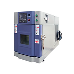
4. Reliability and Environmental Stress Testing
When your project requires additional reliability validation, Thermal Stress Testing, Burn-In Testing, and Environmental Stress Screening (ESS) can be performed under defined stress conditions.

5. Final Visual Inspection
A final manual visual inspection is performed before packaging to check workmanship, cosmetic condition, and visible assembly integrity.

6. Outgoing Quality Control (OQC)
Each shipment includes an OQC report documenting the final outgoing inspection results against the applicable requirements defined for your project.